

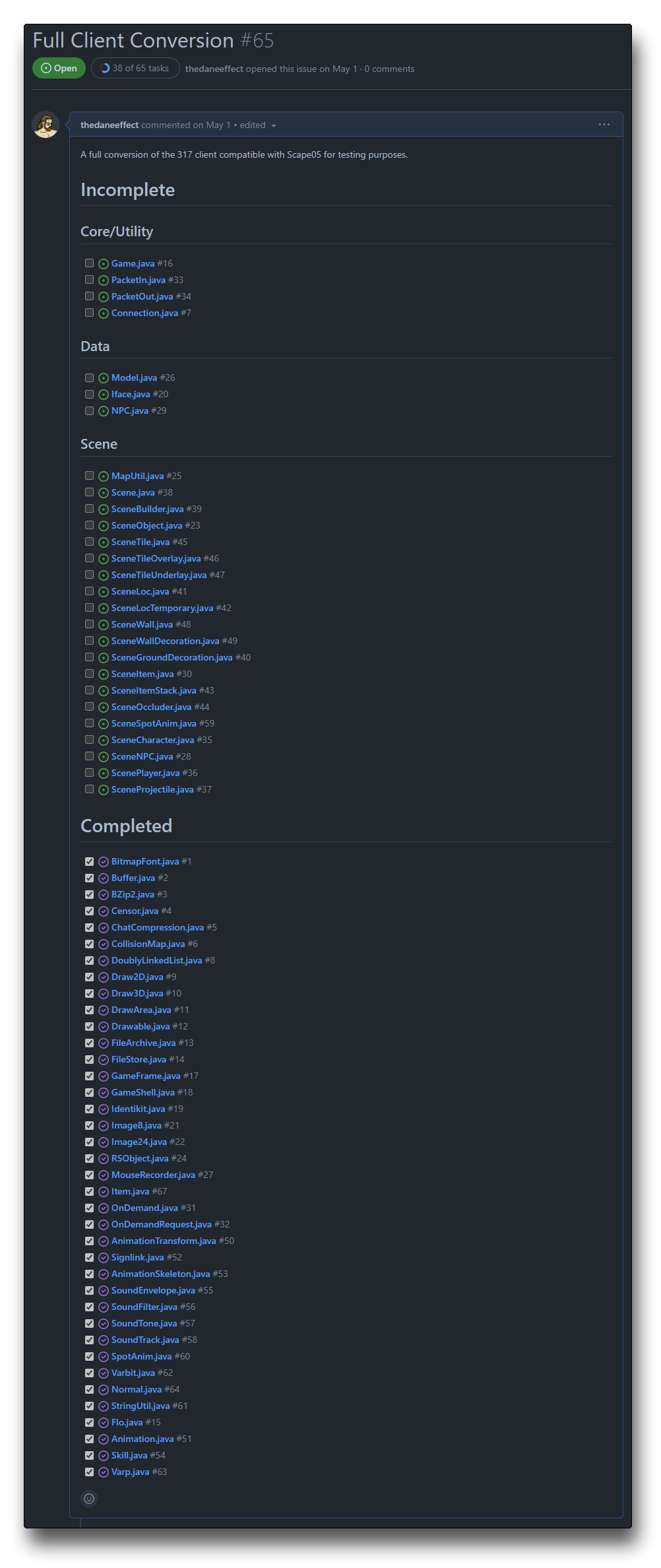
It’s been roughly three weeks since the client conversion officially started, and I’m proud to have made significant progress. In this post, I’ll be explaining my processes and also some interesting inner workings of the game client, particularly in the rasterization techniques used, and of course, the many issues I came across along the way.
(Re)painting a picture
When rewriting an old game engine, it’s vital to ensure the new components work correctly by creating tests. These tests compare the new output to the original engine’s results, serving as a measure of functional continuity. To achieve this, we export data, including numerical and image-based content, from the old engine to serve as reference points. This approach allows us to check that the upgraded engine accurately replicates the original gameplay, facilitating early detection and rectification of deviations.
These tests will prove to be invaluable in the long run when I inevitably do a refactorization process to simplify/enhance/optimize the engine, ensuring that any changes do not break or affect the original appearance of the game in any way.
I’ll skip mentioning the boring primitives such as pixels, lines, and rectangles. Let’s jump straight into the most frequently used primitives:
Standing on the shoulders of triangles
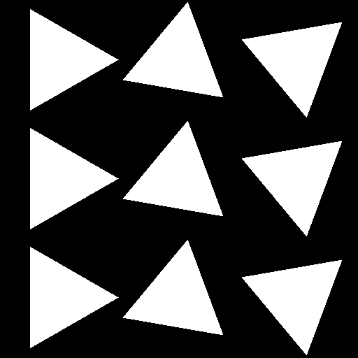
Like most games nowadays, the triangle is the foundation of nearly everything visual. It’s important to get these pixel-perfect for our goals. Luckily there are only three types we need to worry about:
- Flat
- Smooth (Gouraud)
- Textured
Flat triangles are pretty boring, so we can just get them out the way.
Smooth Triangles
Traditionally you would expect smooth triangles to transition between the red, green and blue channels independently, but not in RuneScape 2.
Instead, it interpolates indexed colors pointing to a palette organized by hue, saturation, and lightness (HSL). The way this palette is set up only allows for interpolating along the X-axis or more specifically the lightness.
While this limitation restricts transitioning between two different hues or saturations, it is more computationally efficient and simpler to implement by only having to interpolate a single value as opposed to three.
While this data represents a 128×512 image, the engine will access these pixels as a one-dimensional array indexed by a value formed by the following statement.
(h << 10) | (s << 7) | l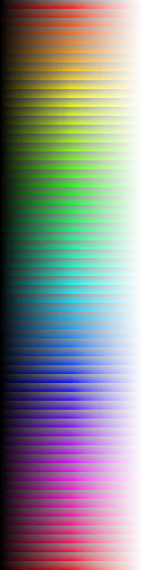
💡 Learn more about indexing
Indexing is the method by which we identify individual elements within a larger data structure. In a list or array of items, for example, we use an index number to directly access a specific item. Each item in the list or array is assigned a unique index number, usually starting from 0 and increasing by 1 for each subsequent element.
In the case of a two-dimensional array (such as an image), you can think of it as a grid with rows and columns. To access a specific element or pixel, you’d need two index numbers – one for the row and one for the column. This is similar to how you’d look up a cell in a spreadsheet by specifying the row number and the column letter.
Now, let’s imagine that we want to simplify this to a one-dimensional index. The concept of “flattening” comes in handy here. Flattening a 2D array (or higher dimensions) means converting it into a 1D array, essentially removing all but one of the dimensions.
To do this with an image (which we’ll assume is a 2D grid of pixels), you can take each row of pixels and just append it to the end of the previous row. You’re essentially creating a long line of pixels, which can be indexed with a single number.
For instance, if we have a 3×3 image (9 pixels total), we can index it in 2D as follows:
- image[0][0] is the first pixel.
- image[0][1] is the second pixel in the first row.
- image[1][0] is the first pixel in the second row.
- image[2][2] is the last pixel.
If we flatten this to a 1D array, the indexing becomes:
- image[0] is the first pixel.
- image[1] is the second pixel.
- image[3] is the first pixel in the second row
- because it immediately follows the third pixel of the first row
- image[8] is the last pixel.
If you’re wondering where the bitshifts came from, they are essentially just efficient multiplications.
| Bitshift | Equivalent | Reasoning |
|---|---|---|
| x << 7 | * 128 | Each row is 128 pixels. |
| x << 10 | * 1024 | Each hue is 1024 pixels (128×8). |
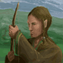
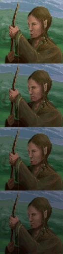
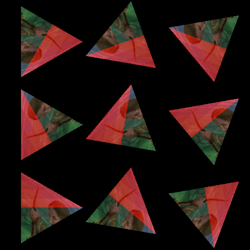
Right, so here are the triangles using the HSL values 0, 64 and 127. The left was rendered in Java and the right in Go.
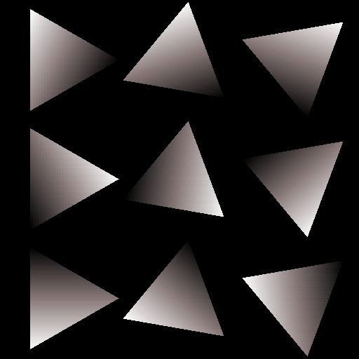
Java
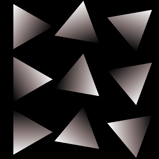
Go
While these results appear to be identical, they are in fact not. Note: the largest error is 4 out of 255, meaning ~1.57% error worst-case scenario which is hardly perceptible.
Upon writing this I still don’t know what exactly the difference is. I know that the int type in Java is supposed to be the same as int32 in Go, which is what I wrote that function to use. But there still seems to be an error in the color stepping that I can’t isolate. To be honest, the Go result is smoother and I don’t want to crawl down a rabbit hole, so I just consider this a non-issue and move on.
Textured Triangles
All textures are 128×128 and the function for textured triangles also assumes this for efficiency. Traditional methods of texturing triangles involve UV mapping, which surprise: this version of the game doesn’t use. Instead, the mesh data describes a plane in model space, in which the texture exists and gets projected onto the triangle in viewspace.
The implementation is described here. I’m not sure what made this solution better than simply UV mapping. My only thought is that it somehow provided simpler/more efficient perspective-correct projections as opposed to the traditional 1/z interpolation.
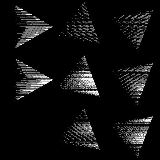
There’s an interesting optimization used to turn shading for textured triangles into simple bitshifts. A texture is transformed into 4 copies of itself, each copy darker than the previous. It looks like we’re limited to 4 shades but there’s an additional hidden feature allowing us to have 16 total shades. From here we’ll refer to this working copy of the texture as texels.
During generation, each texel’s red and green channels have the 3 lowest bits cleared. This effectively allows us to use binary right shifts to halve, quarter, or eighth the value of our colors without the green channel spilling into the blue, or the red into the green. We don’t have to clear any blue bits since they just get chopped off when we shift right. So the cost of having 3 more levels of shade is having 3 fewer bits to represent red or green. In this style of game, those missing bits won’t be noticed.
The line of code for clearing those bits is a single operation:
texels[i] = rgb & 0xF8F8FF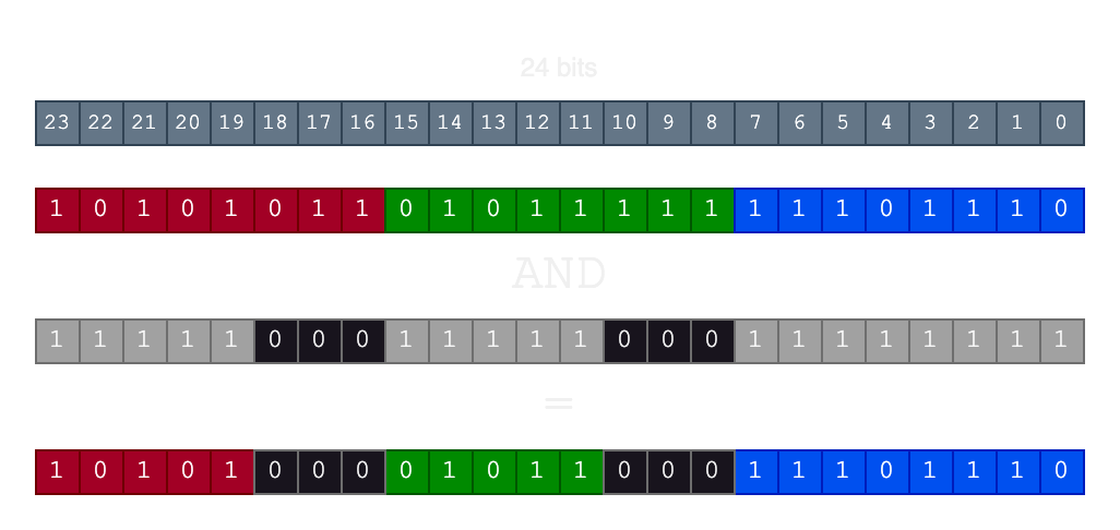
If you’re not familiar with binary, a single right shift is the equivalent of dividing by 2. Looking at the diagram above you can imagine moving the RGB channels to the right up to three times. Finally, this yields us the equivalent of a 512×512 image that would look like this:
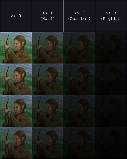
Perfect! Now we can just plug these texels into our fill triangle function and…
Oops. After all of this, I forgot that my rewrite will be keeping track of the alpha channel for future usage. Since I didn’t clear the lower bits of the alpha channel it spilled into the red. Since alpha isn’t a part of the shading process we can just strip it entirely.
Finally, we have all three techniques working as expected and passing their unit tests. We can move forward onto more complex geometry safely.
Putting them all together
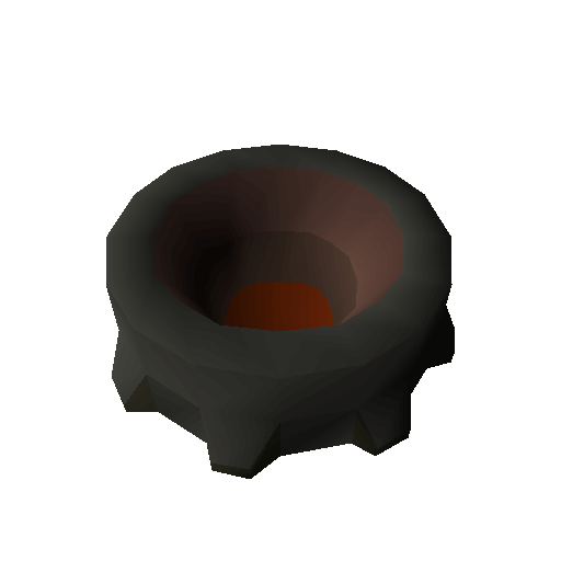
I made a table for satisfying the possible triangle options and then searched for models which fit the bill.
| Mode | Opaque | Translucent |
|---|---|---|
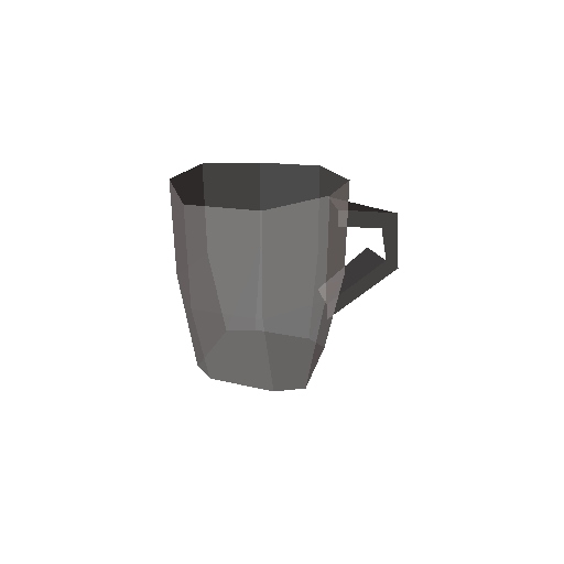
| Flat | Skipped | Beer glass |
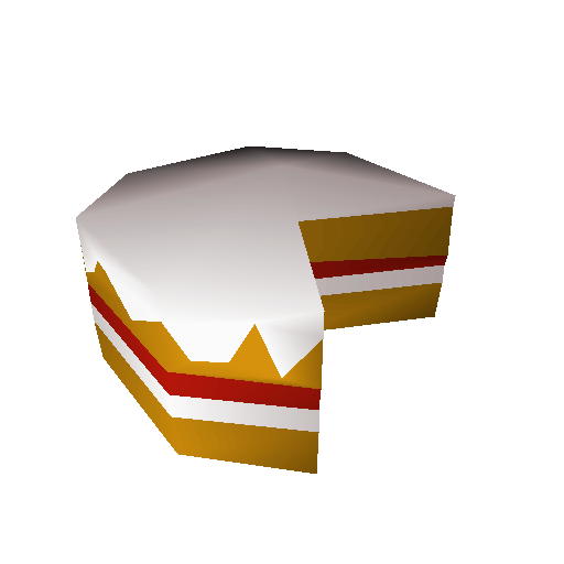
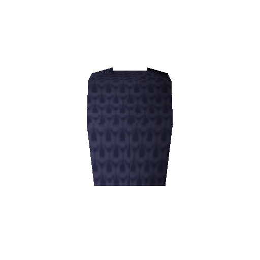
| Gouraud | Cake | Mithril Chainbody |
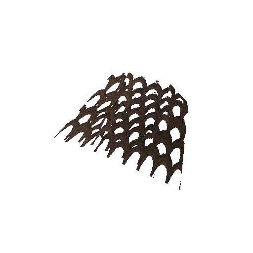
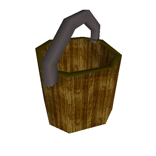
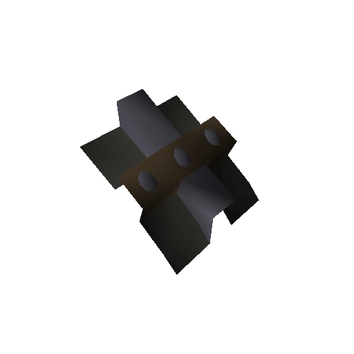
| Textured | Mithril Chainbody + Bucket | Fishing Net |
These seemed like a diverse enough set of models to test. I should mention that I chose a rather verbose way of comparing models, not just visually but data- wise. This will be even more important later when we start manipulating the models since we need the data to be identical.
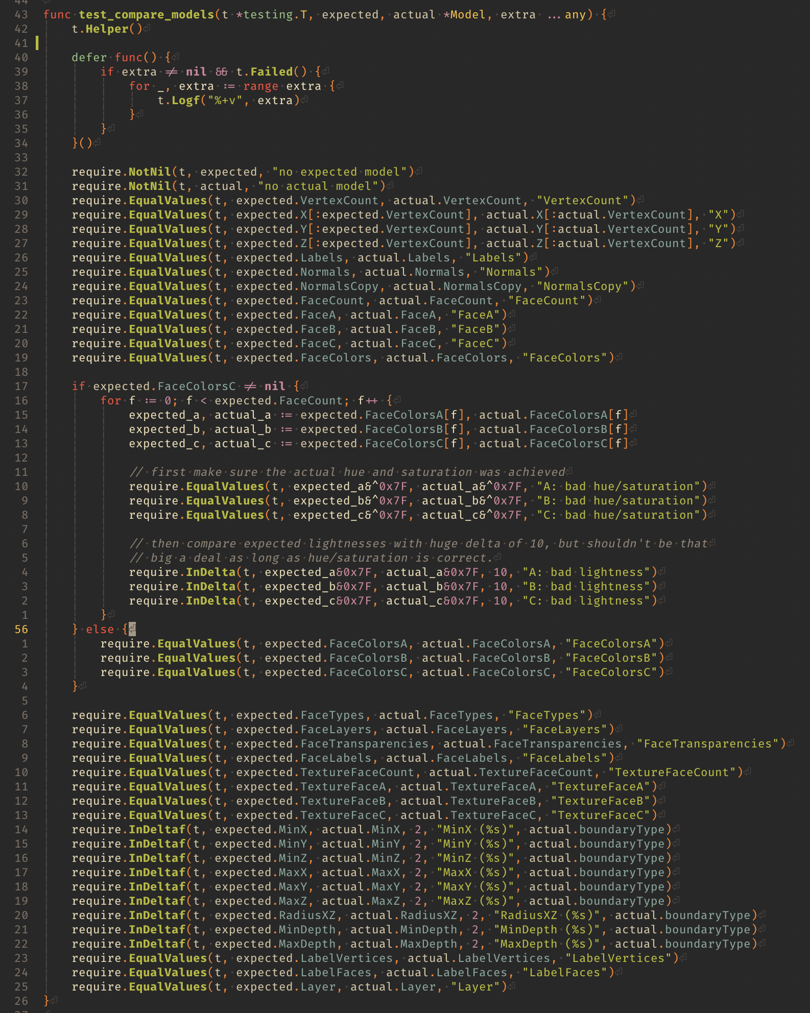
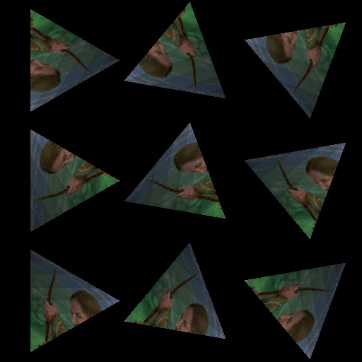
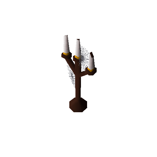
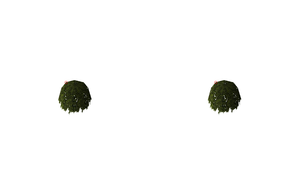
Additionally, it quickly became apparent I would need some way to visualize programming errors instead of just data. I wrote a simple utility function to complement my tests which compares two images and exports an image with a red circle around the failing pixel.
Here’s an example of one of our test suite models failing:
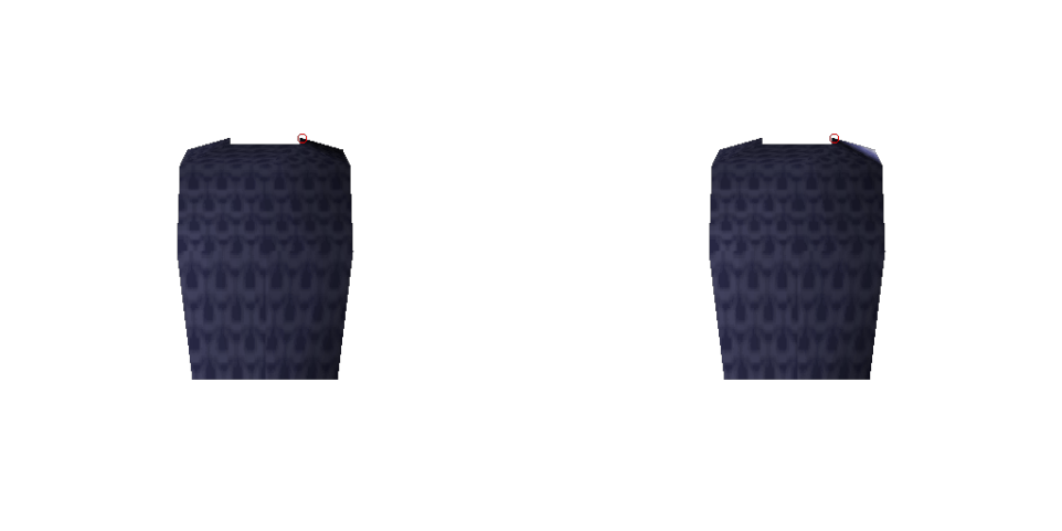
Java (Ground truth) and Go (Failing) respectively
It took me a minute to track the problem down, but luckily I narrowed it down to the function used to calculate the lightness of a normal for a given light. I was casting the result to uint16, which was not a smart idea since the result comes from a dot product whose value can be negative. Super simple fix.
func normal_lightness(n Normal, ambient, contrast, x, y, z int32) int32 {
	return ambient + (x*n.X+y*n.Y+z*n.Z)/(contrast*n.W)
}
Fortunately, this suite of tests revealed a few oversights such as the palette being generated off hue which was also an easy fix. Smooth sailing so far.
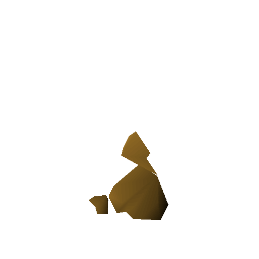
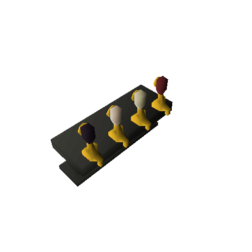
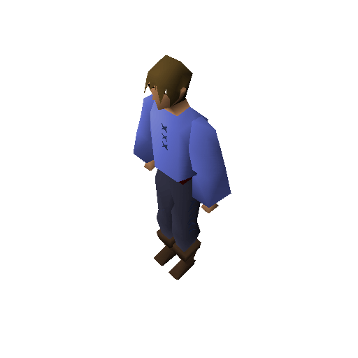
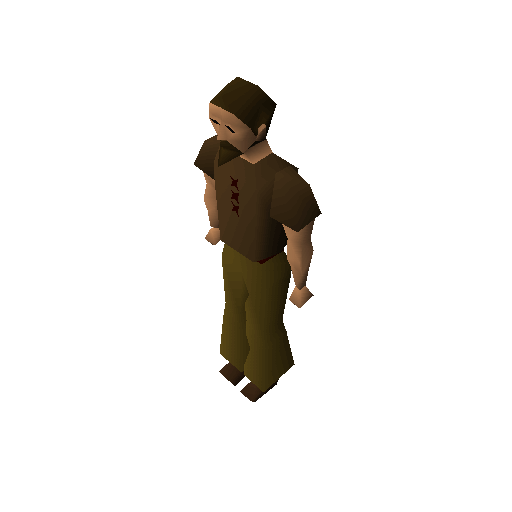
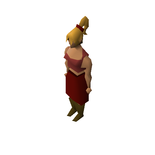
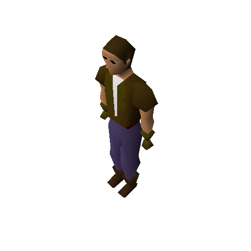
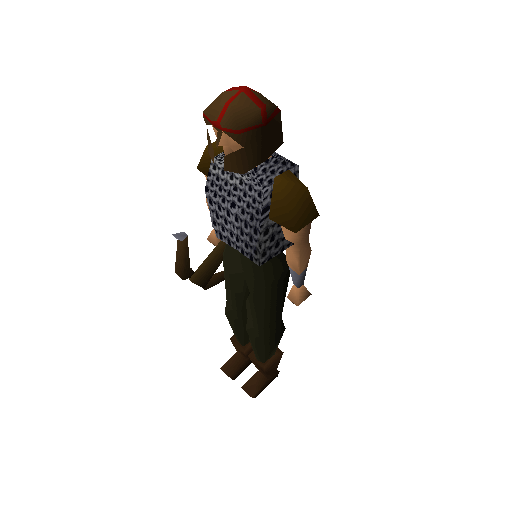
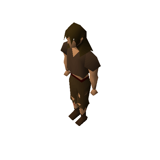
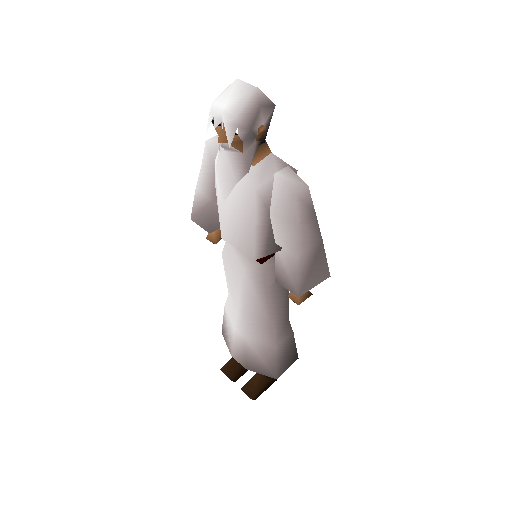
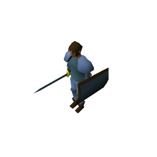
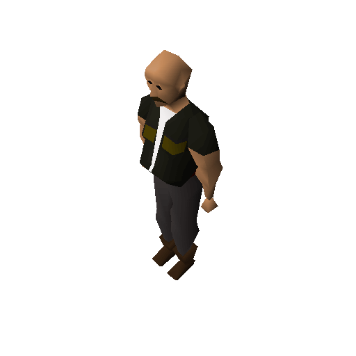
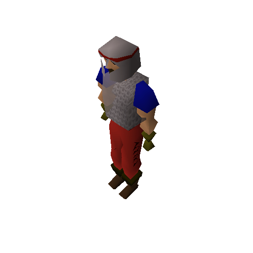
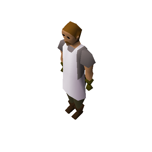
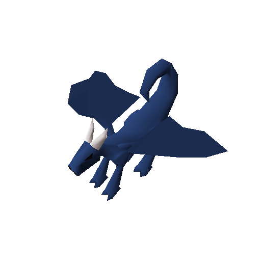
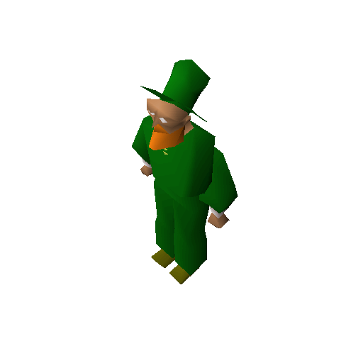
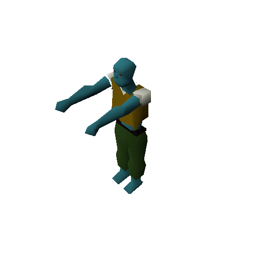
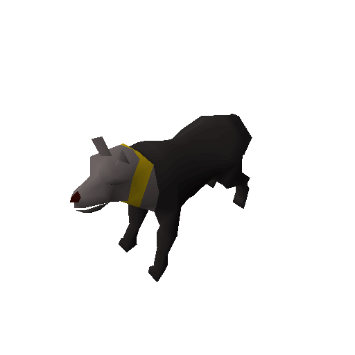
Building our Bob
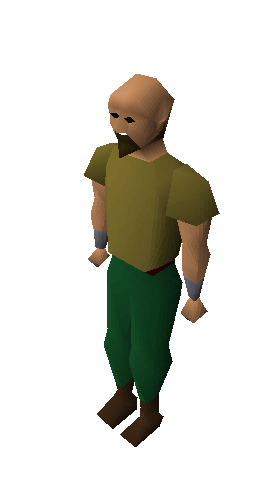
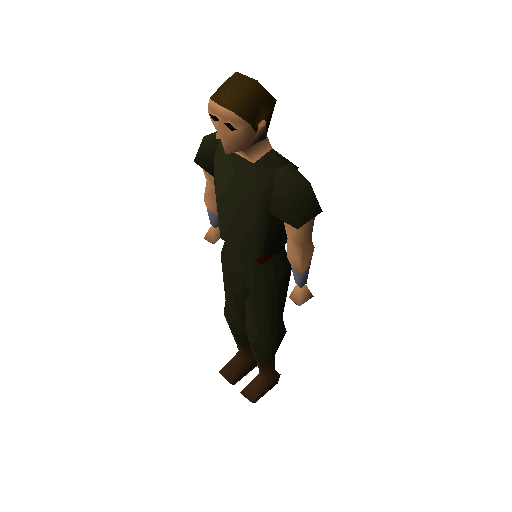
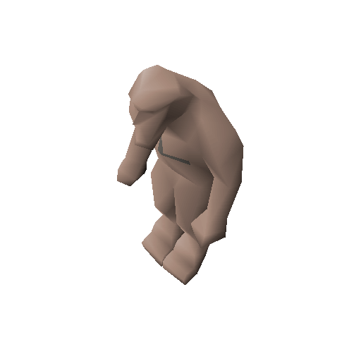
The next natural progression seemed straightforward, joining models together. This gave me an opportunity to bring in Identikits, which are used to describe parts of a player character’s body. Here’s Bob:
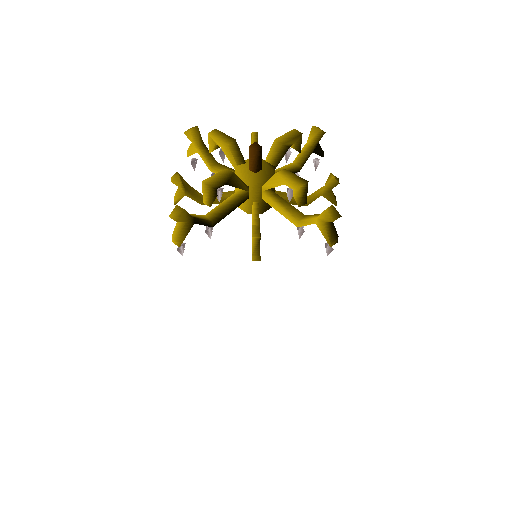
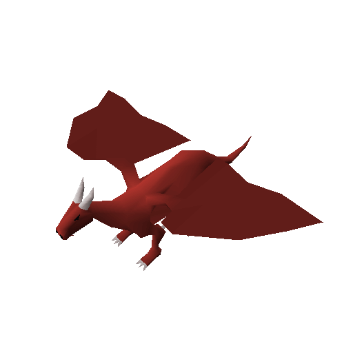
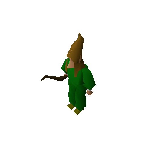
The player model has complexities such as “layering” (aka priorities) and is an odd enough shape to do some depth-sorted triangle testing. So I set up some more bobs at differing pitches and generate a ground truth image to ensure identical results.
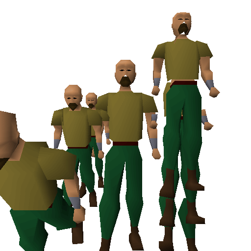
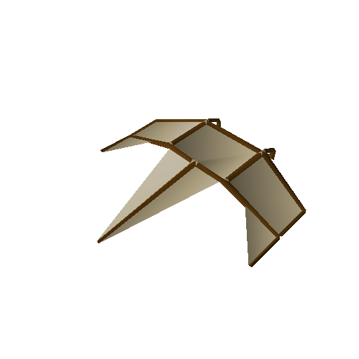
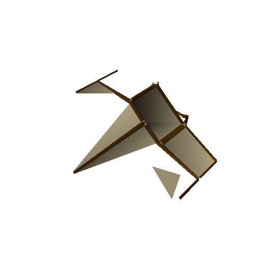
You might notice some floating parts. An odd artifact of the depth sorting algorithm used in the client seems to prefer that models don’t rotate backward away from the camera. This has to do with the way the client defines the maximum depth range it should expect a given model to use. Looking at Bob from the side profile you would see he’s quite narrow, which gives us a narrow depth range. This boundary is typically only calculated once after “building” a model which is why it’s possible to rotate a mesh outside of its boundary.
He can rotate forward because of the loop used to access depths starting at the calculated ‘max depth’ and decrementing to zero. Here’s a side profile of the effect:
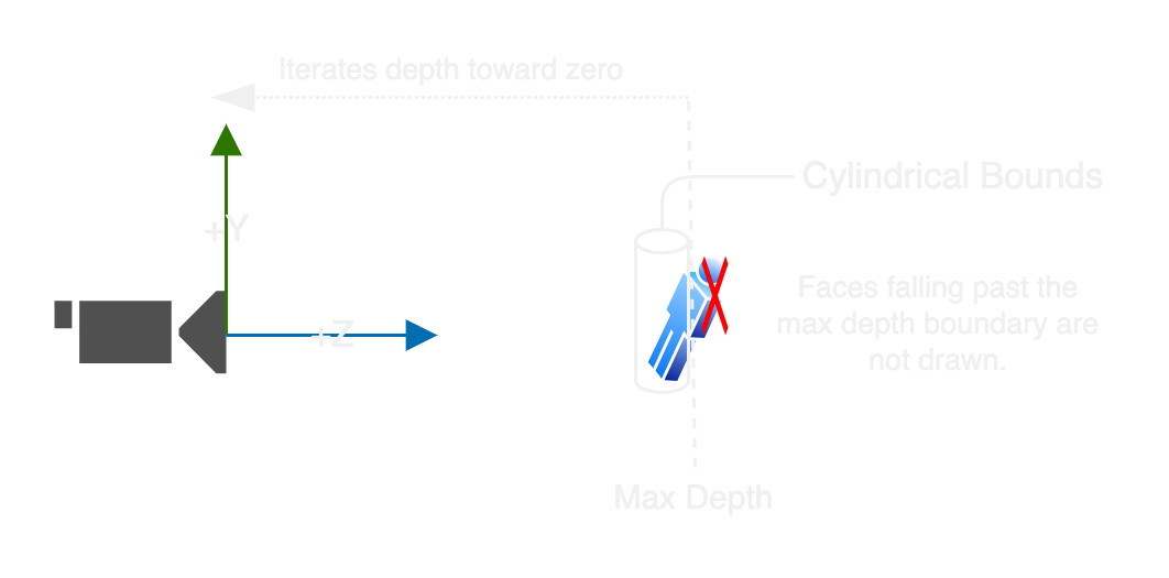
The actual depth sorting of the engine is done by having preallocated a mapping of depths (up to 1500) to a list of faces (up to 512) and populating them before a model starts drawing. This is done in Java as a 2D array indexed by [depth][n] with n being the nth face in that depth, and the resulting value is the face_index. Here is the implementation on GitHub.
Bob desires ITEMS!
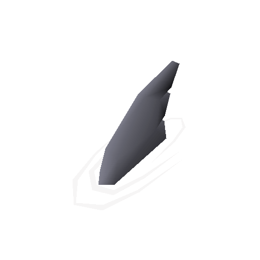
Items were extremely simple to implement. They’re basically only configurations. I did end up making a test to compare every single inventory icon which pretty quickly passed…
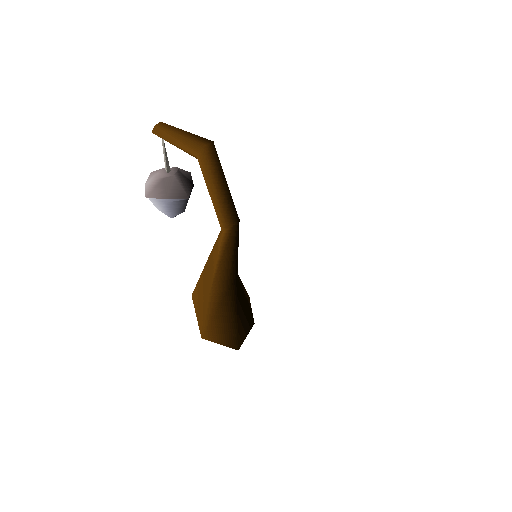
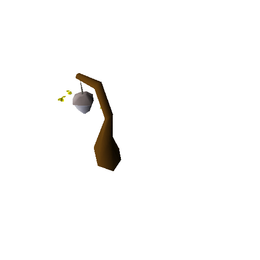
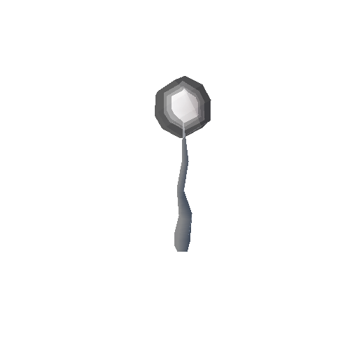
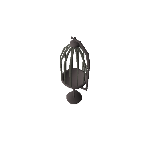
EXCEPT, for one thing: this seemingly stray bit of icon. The bullseye lantern and the sapphire bullseye lantern shared the same exact problem.
I was troubleshooting for a day, going as far as keeping track of stack traces for each pixel so I could pinpoint exactly what was going on. While I was in the middle of stepping in my debugger between the Go runtime and Java, it dawned on me… The rasterizer in Java doesn’t output an alpha channel, only RGB, and when I export the image I’m checking if a pixel value is >= 0, then set that pixel to opaque. But this excludes perfectly black pixels, which I had incorrectly assumed weren’t allowed to be used. My solution ended up being to set all the pixel values to 0xAA000000 before drawing the icons and using that value to determine if a pixel was modified or not. This worked perfectly and I had a passing test for item icons.
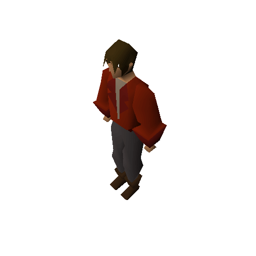
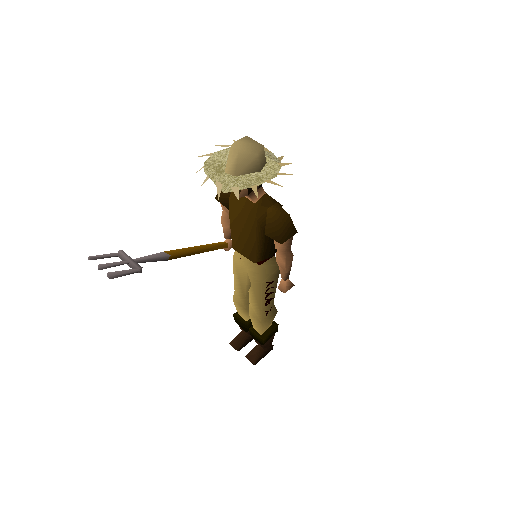
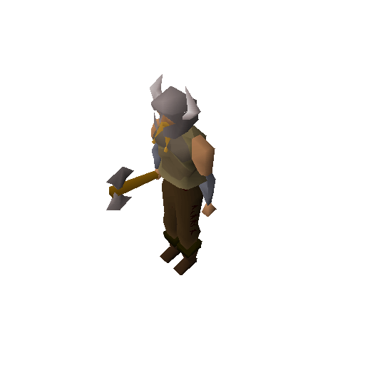
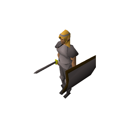
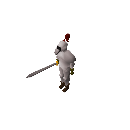
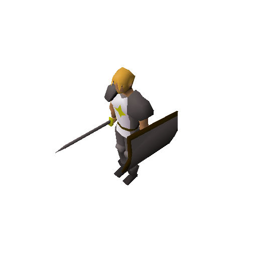
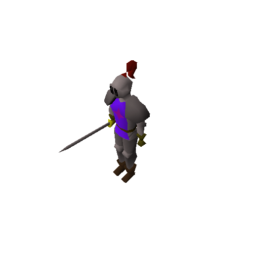
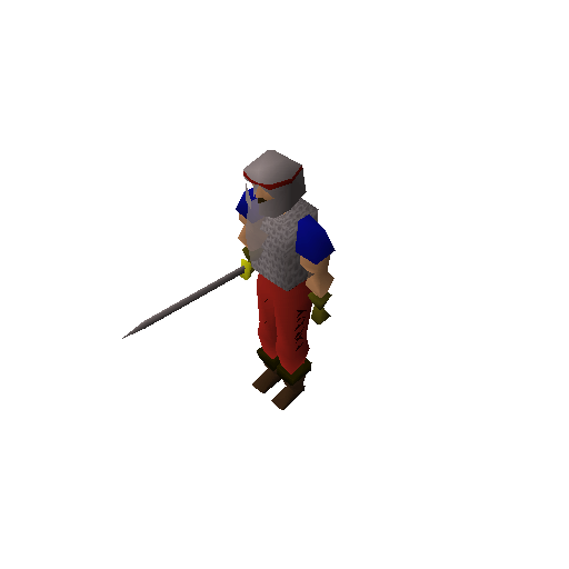
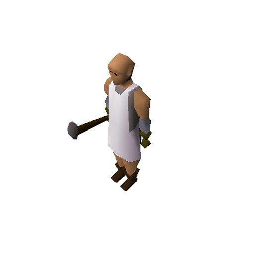
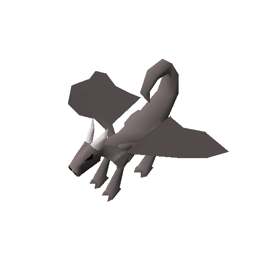
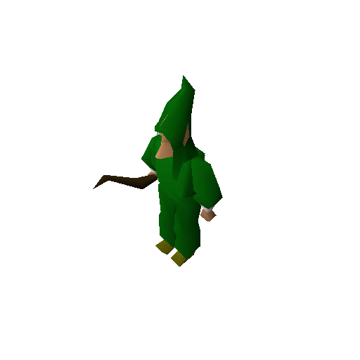
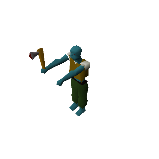
Finally moving on and getting Bob some cool gear.
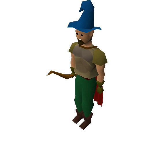
Although… he’s looking a little stiff.
Bob needs to loosen up.
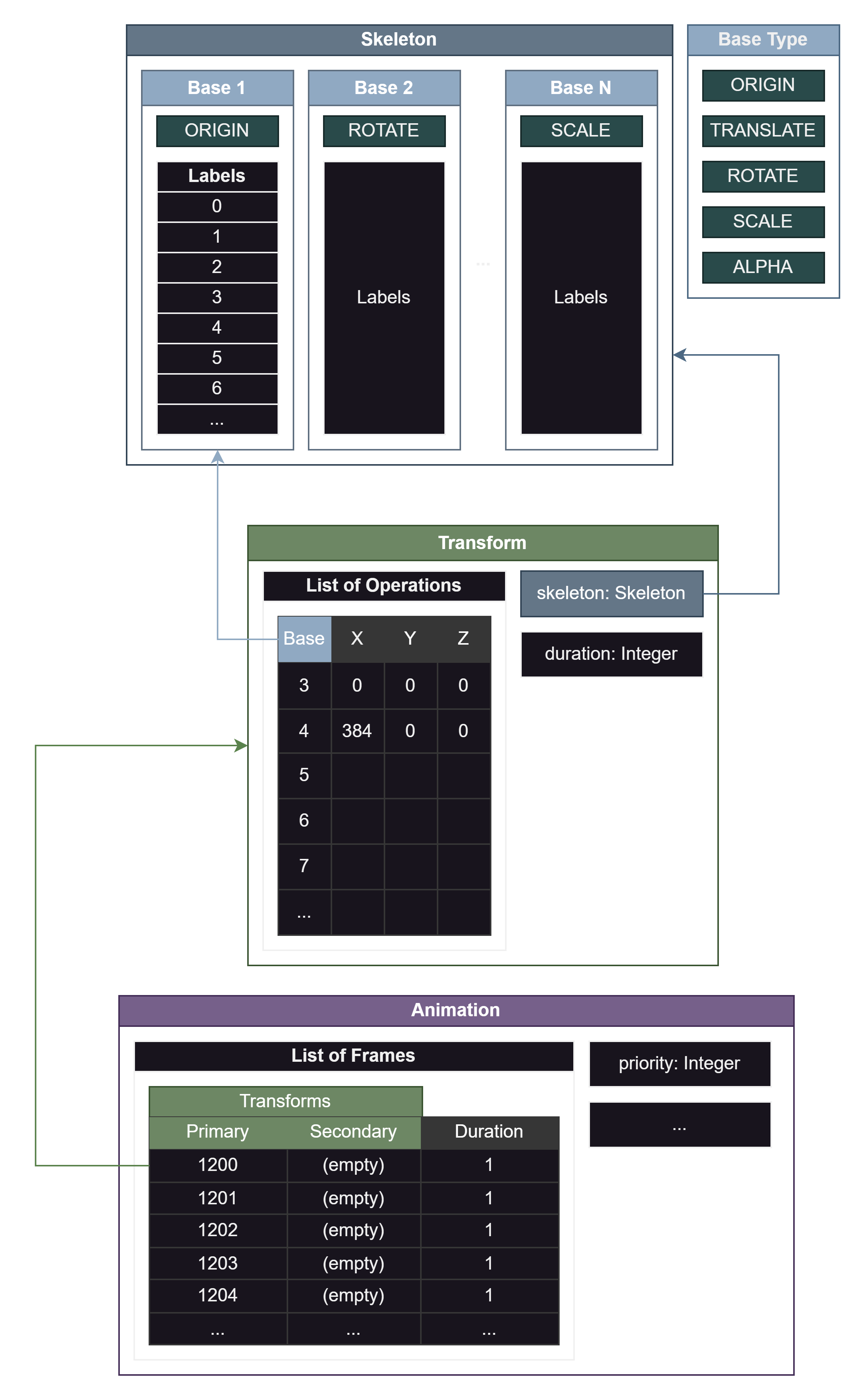
Once again, the implementation of a core feature is done differently than you would expect. Traditional methods of animating a mesh involve rigging using a hierarchy of bones representing a skeleton and using transformation matrices for each bone to define its orientation. RuneScape doesn’t take this approach.
Let’s start with introducing the building blocks so that terminologies make more sense. I’ve laid the following out in an order that ensures each concept builds on the previous:
- Label
- If you’ve heard of weight painting before, the rigging process involves assigning a “weight” of influence a bone has to any given vertex in a mesh. In RuneScape, the weight is either 0 or 1 depending on whether a Label is assigned to a given vertex or face.
- Base
- Holds a set of Labels that this Base will influence.
- Describes the type of transformation this Base performs. These are the available options:
- Origin
- Translate
- Rotate
- Scale
- Alpha
- Skeleton
- A glorified container of Bases and nothing more.
- Transform
- Contains a list of operations, each of which describes the Base they use, along with the parameters X, Y, and Z.
- Animation
- Contains a list of Frames, each which describes a Primary and Secondary Transform along with a Duration. Most animations will not have secondary transforms.
- Contains other additional data related to held item overrides, render priority, etc…
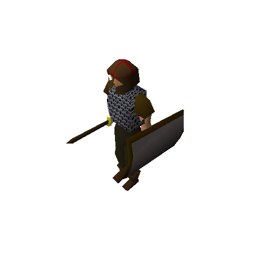
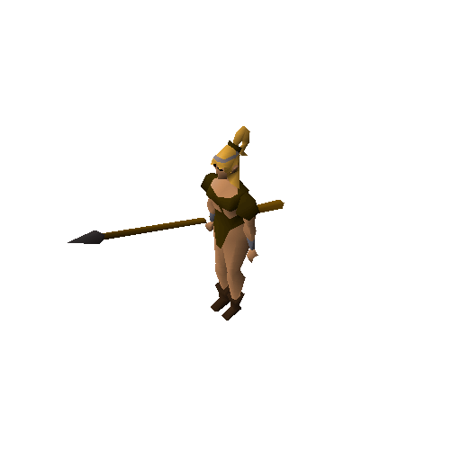
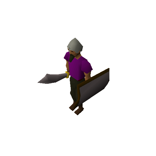
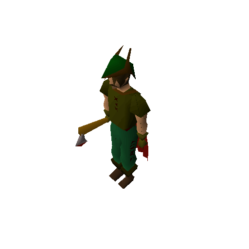
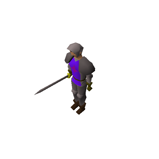
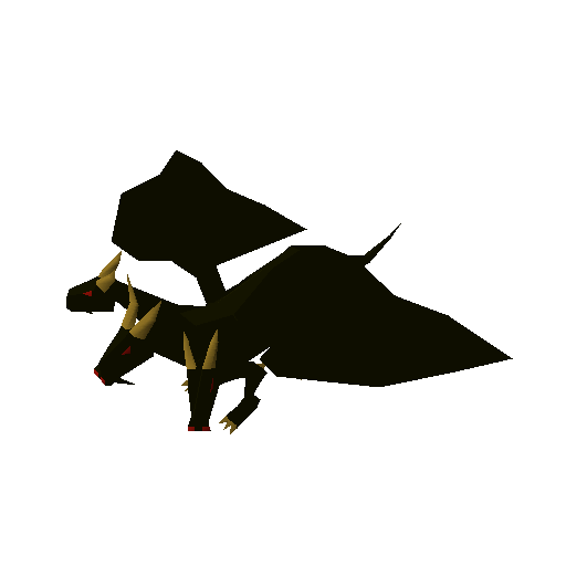
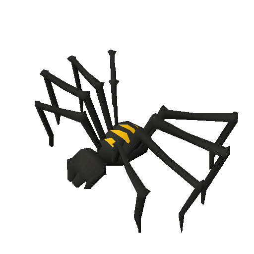
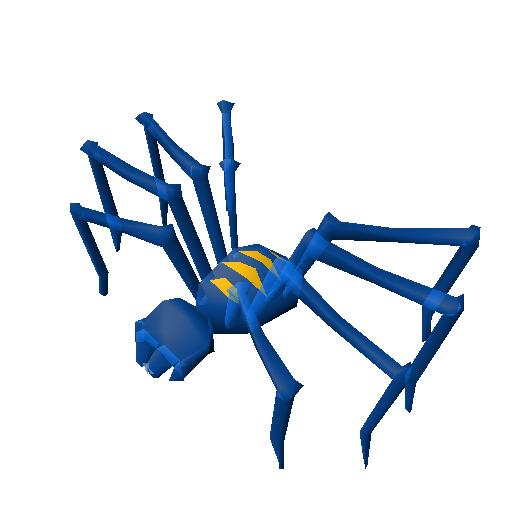
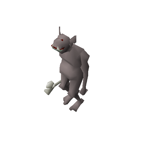
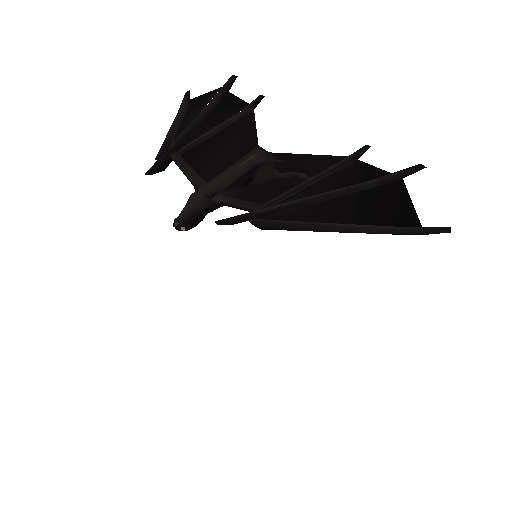
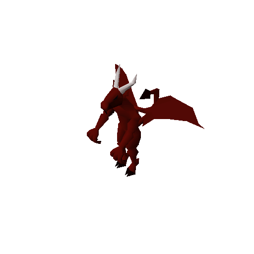
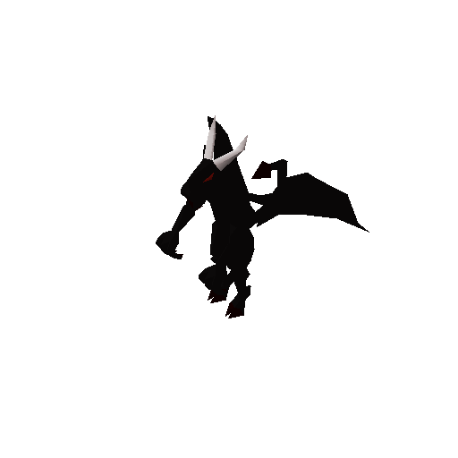
Finally, Bob can do something with his newfound gear. Unfortunately, he woke up and chose violence.
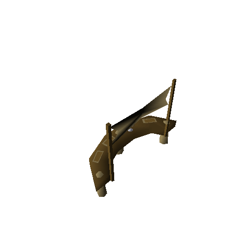
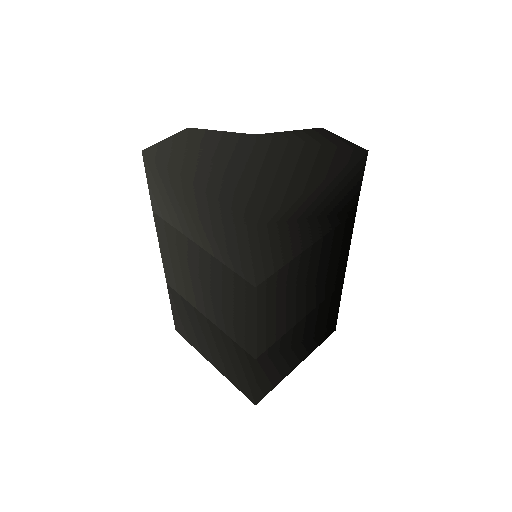
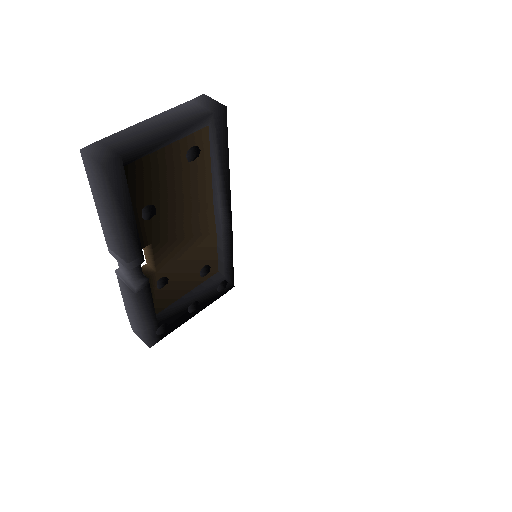
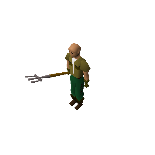
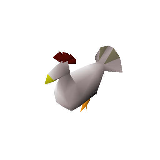
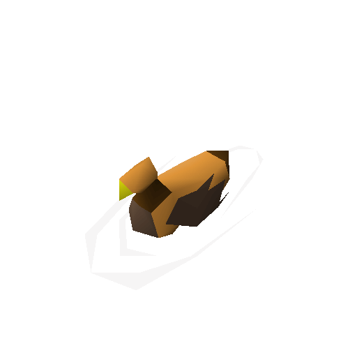
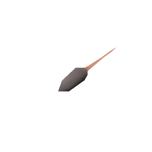
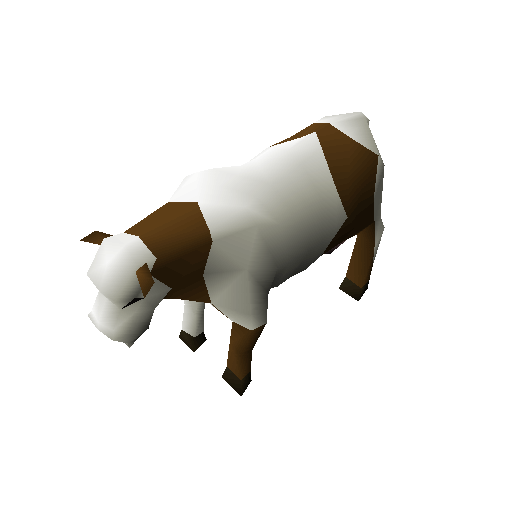
Our world is empty without objects
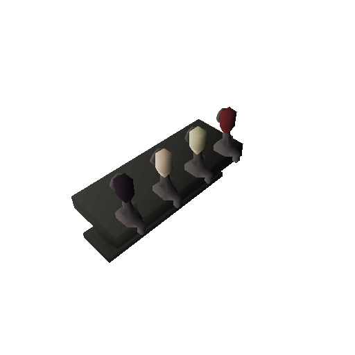
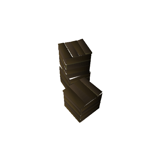
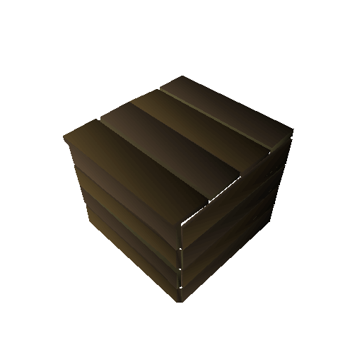
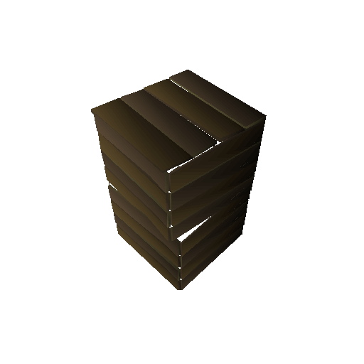
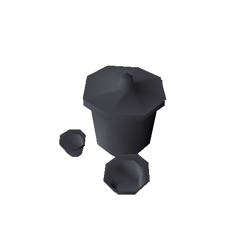
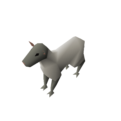
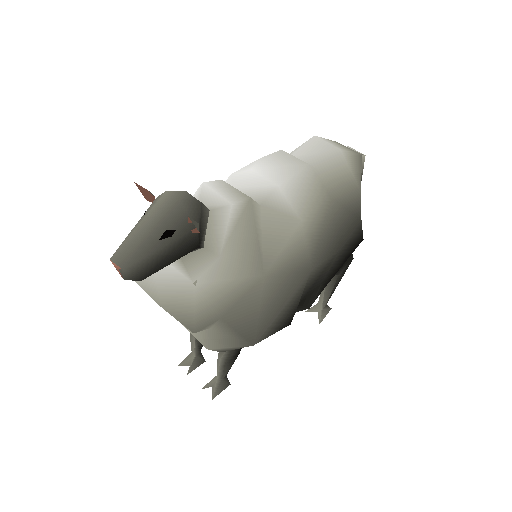
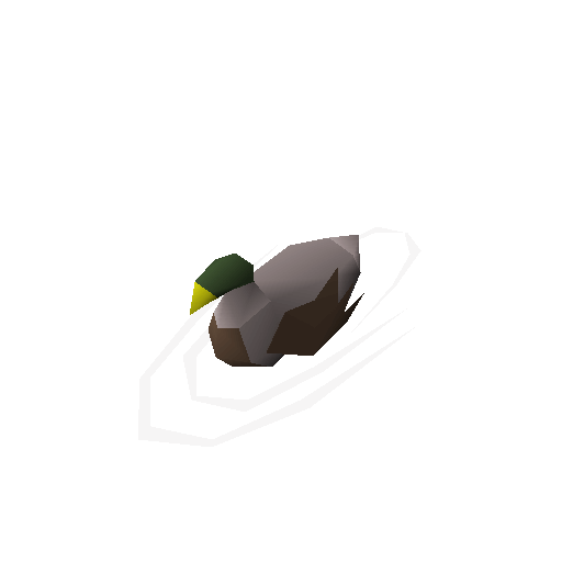
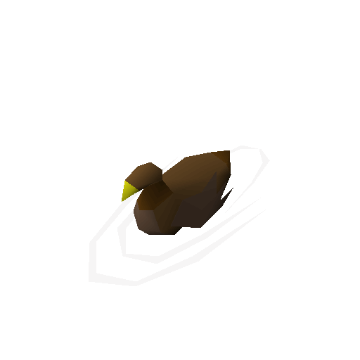
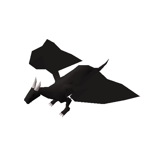
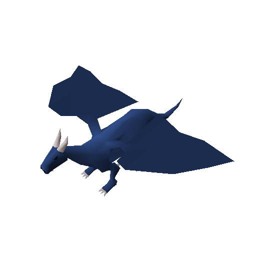
Pretty much the same story as items: Objects are basically just configurations and the most important part will be just making sure they look right! Here’s a bunch of “ground truth” images of objects for your eyes to feast upon:
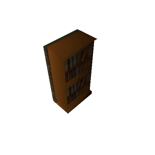
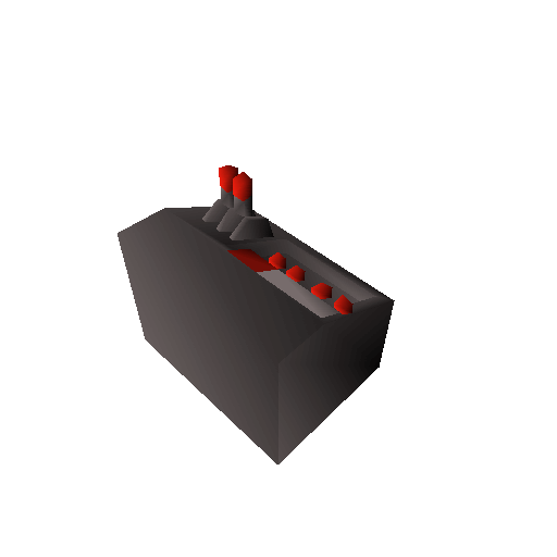
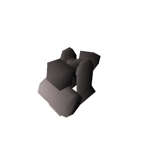
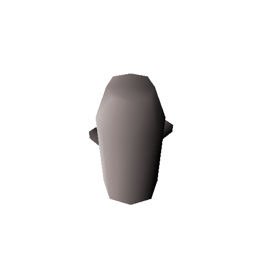
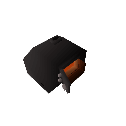
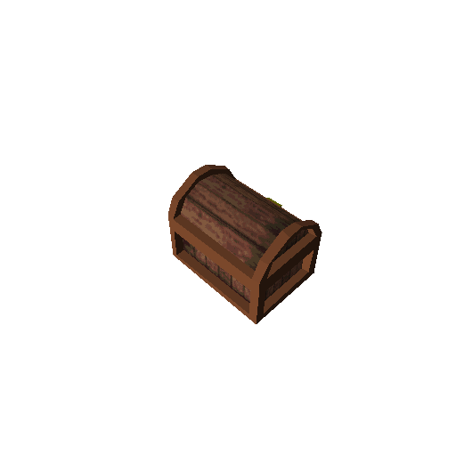
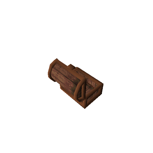
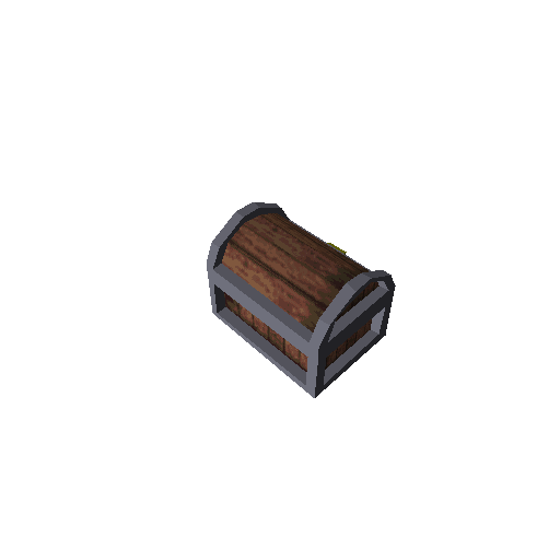
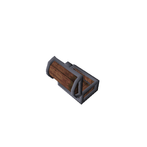
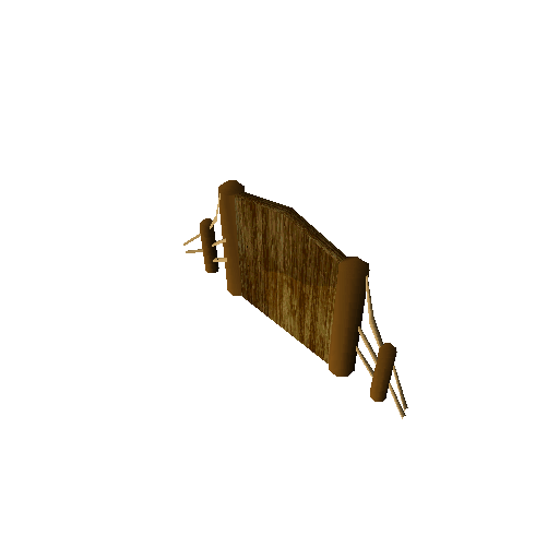
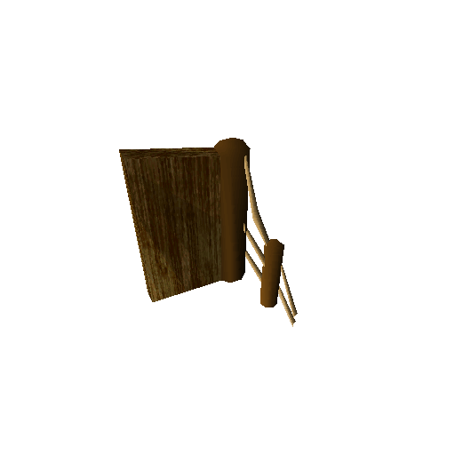
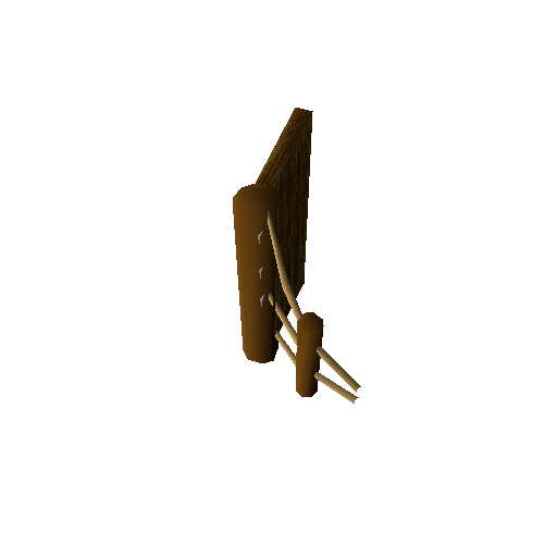
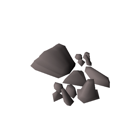
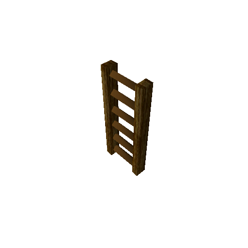
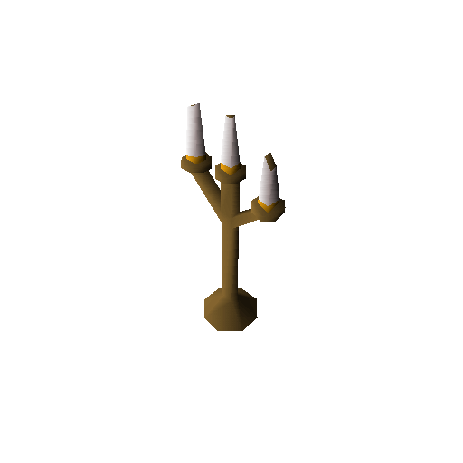
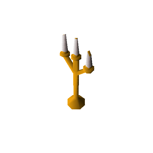
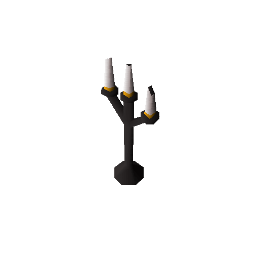
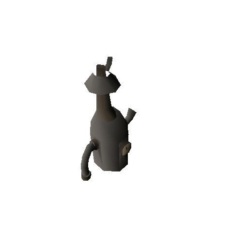
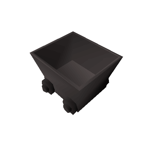
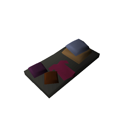
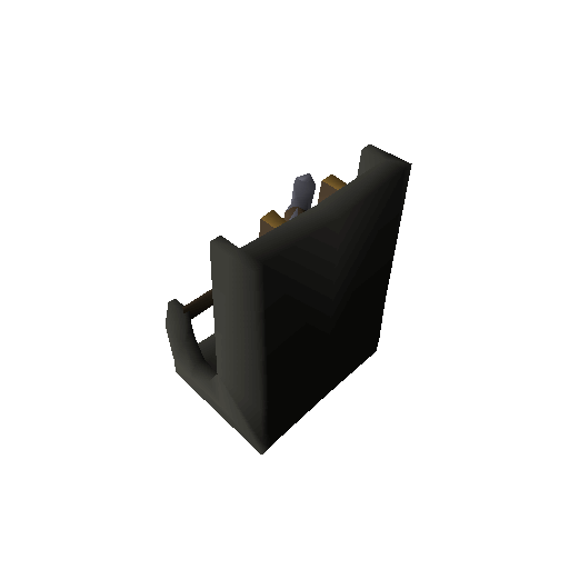
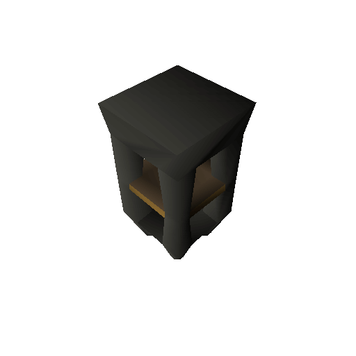
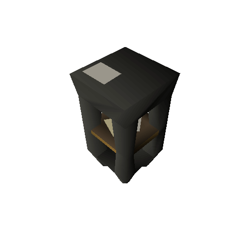
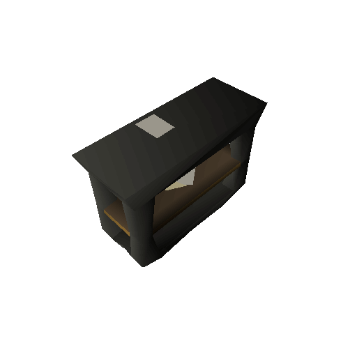
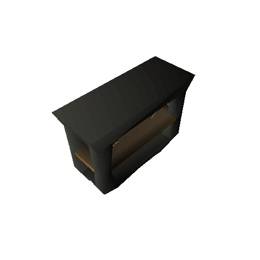
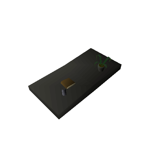
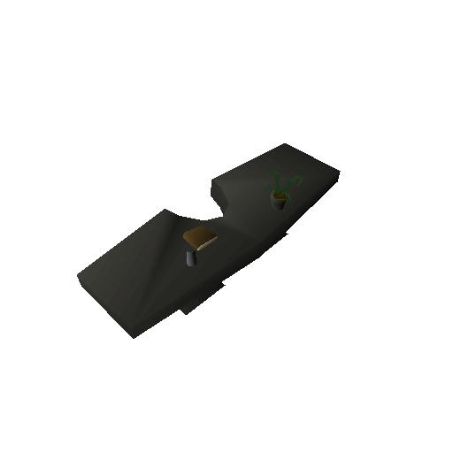
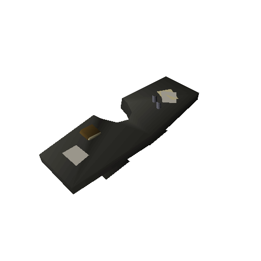
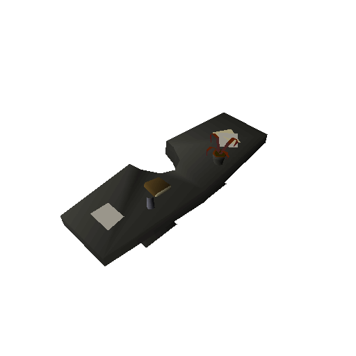

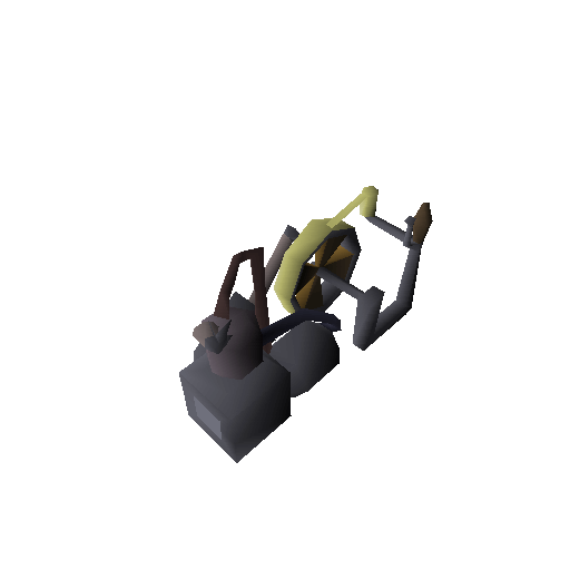
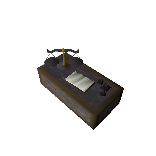
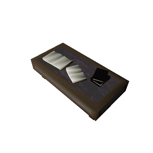
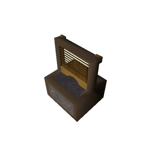
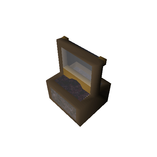
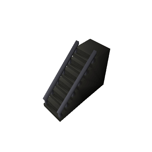

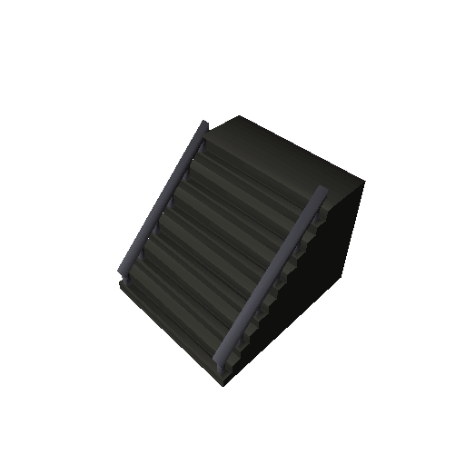
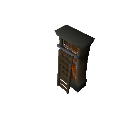
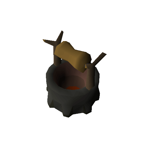
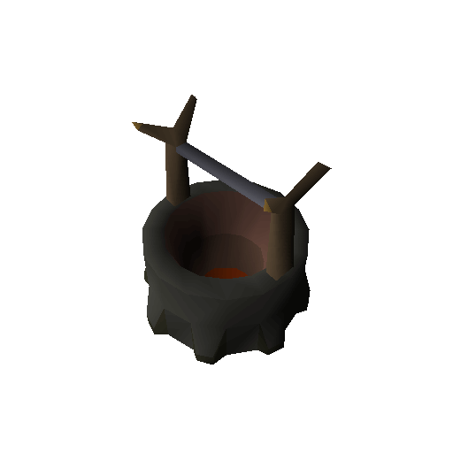
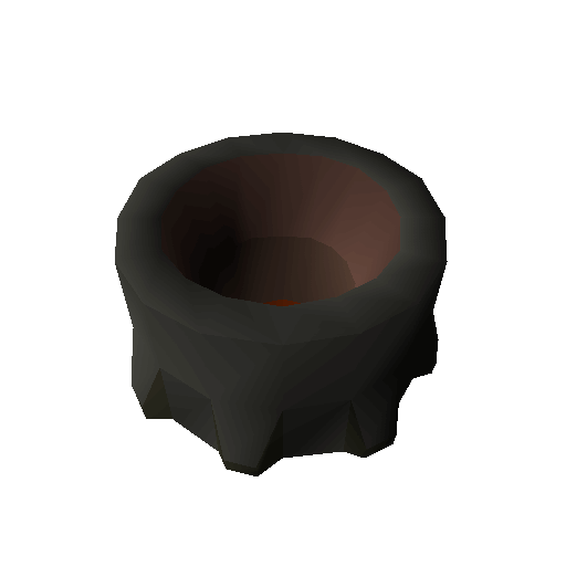
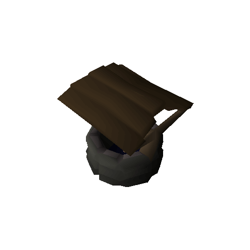
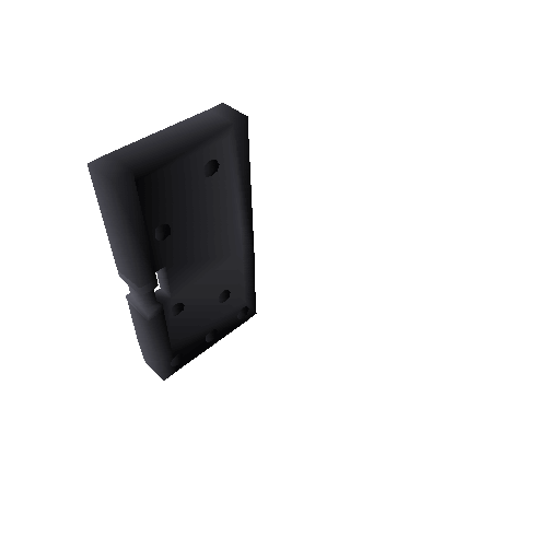
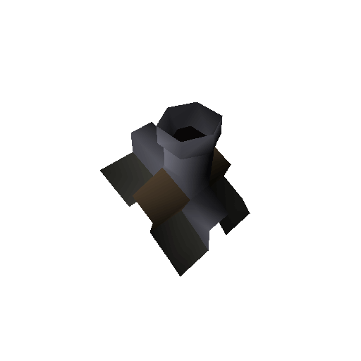
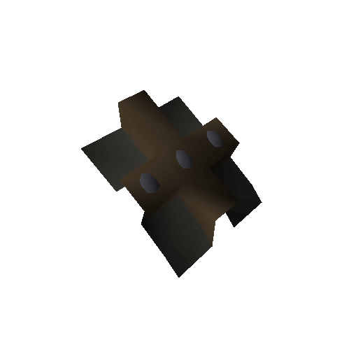
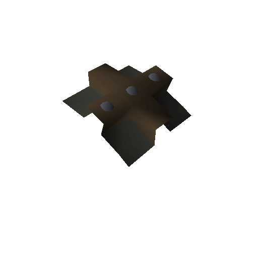
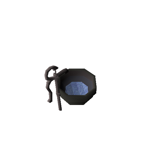
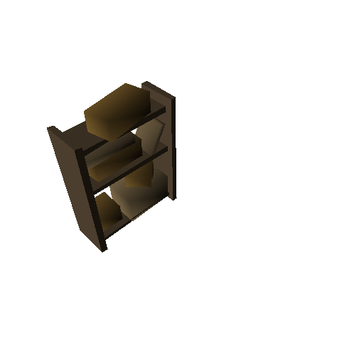
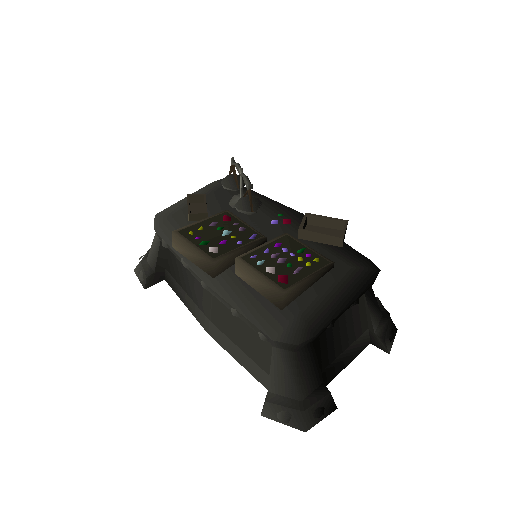
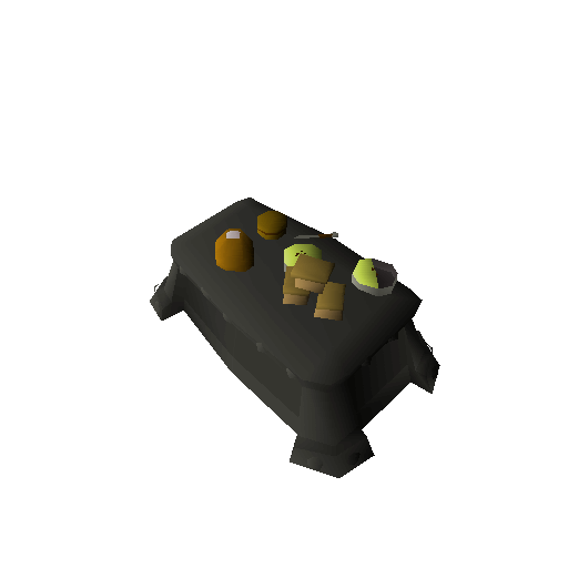
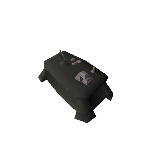
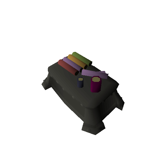
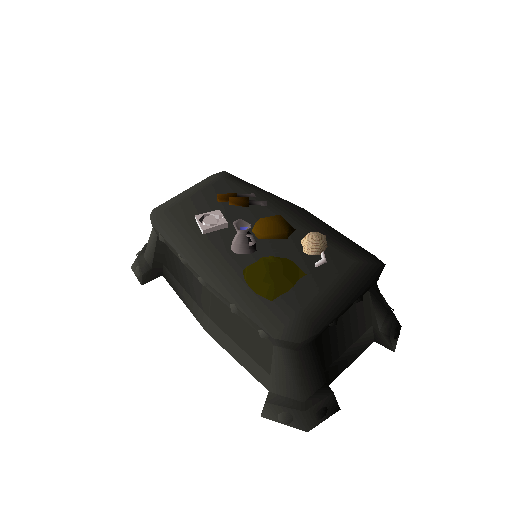
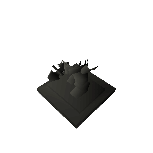
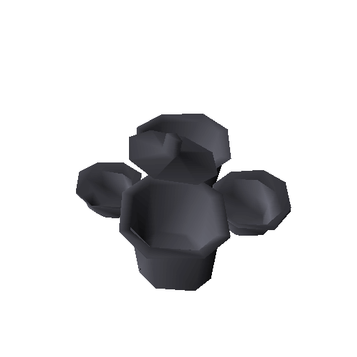
Everything works as expected, except for some complaints about noisy textures. It’s hardly noticeable but occasionally there will be an ENTIRE pixel missing from the output.
Luckily I know the cause of the inconsistency… and won’t be fixing it. It’s
because Java uses 32bit integers and my implementation is using 64bit. There are
some small differences and probably some performance implications, but for now,
I’m not worried about it and consider it a non-issue.
4 June 2023 – It turned out to actually be something else. Holes are allowed in a texture when it is flagged as “masked” and the fetched texel is zero, however, I had glossed over the fact the original textures used a palette system and only allowed the first color at index 0 to be masked away. Since I neglected to use a palette (I am now) I ran into the problem of some textures with near-black texels becoming effectively black in their generated shades.
I think I can rest soundly knowing that my texels are now truly 1:1 to the ground truth and I’m not just going crazy just yet!
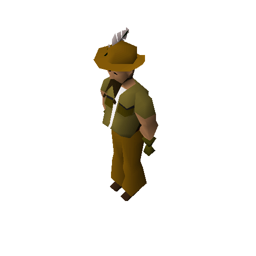
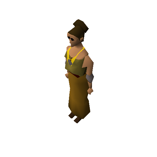
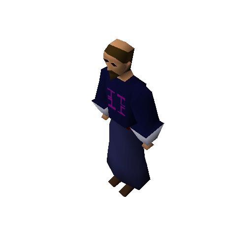
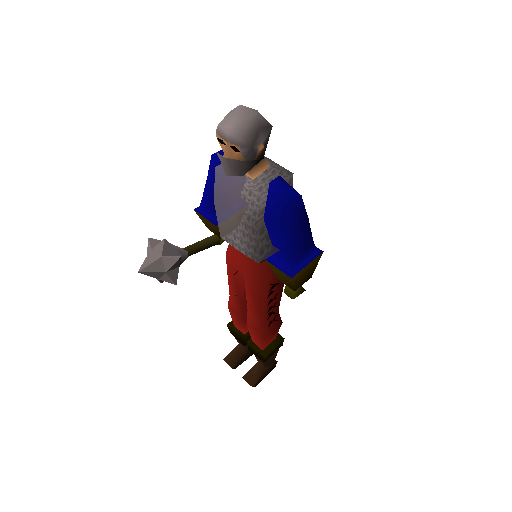
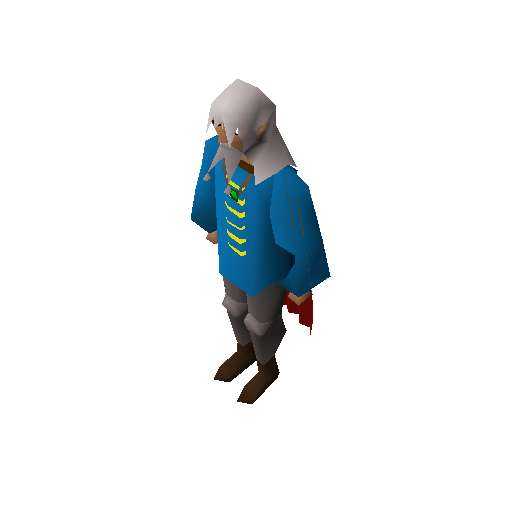
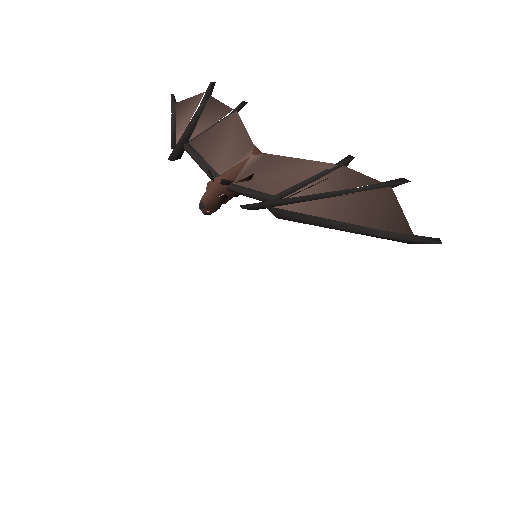
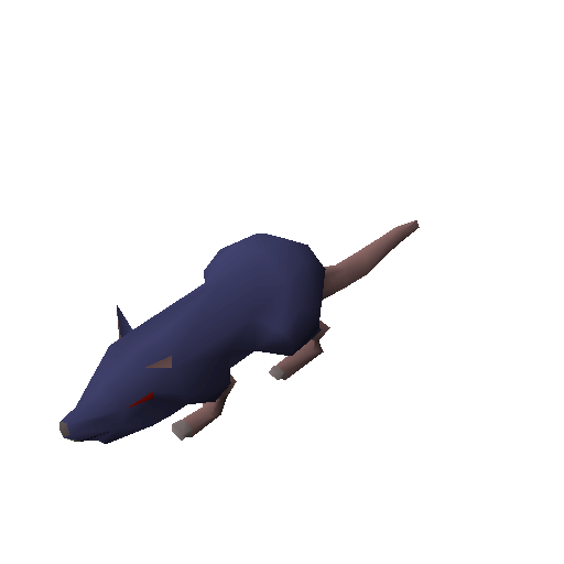
Our world is dead without inhabitants
Here’s a gallery of 95 NPCs for your viewing pleasure.
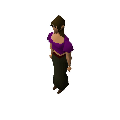
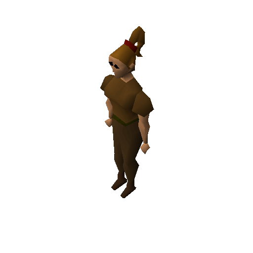
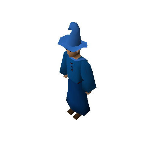
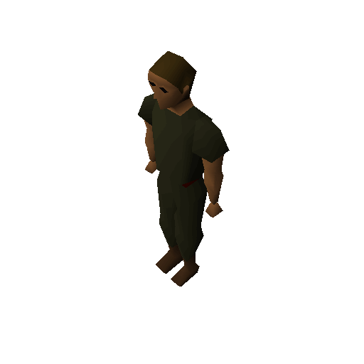
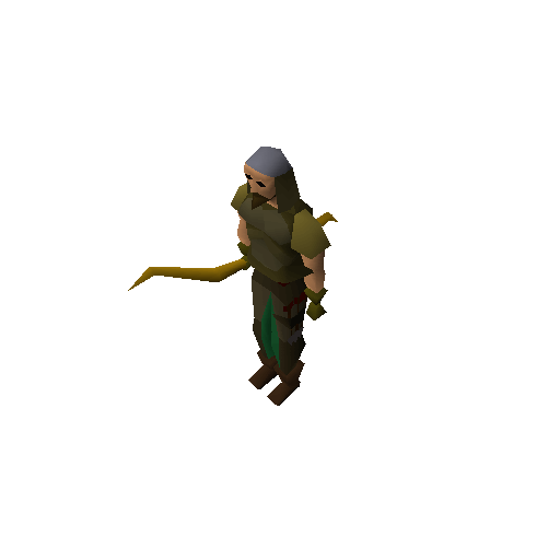
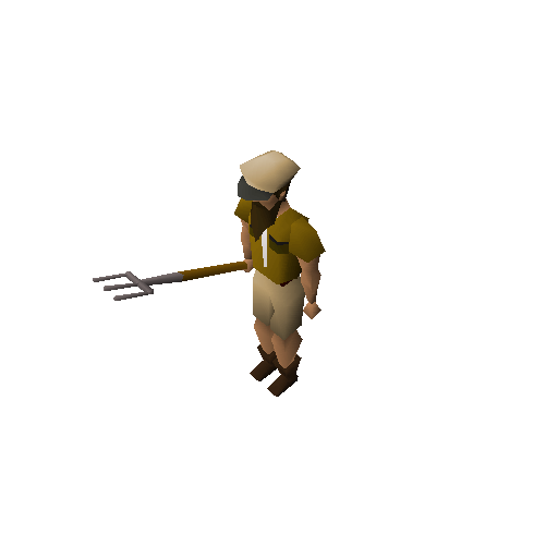
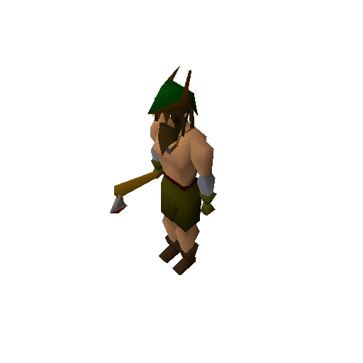
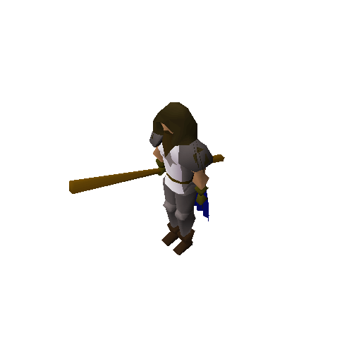
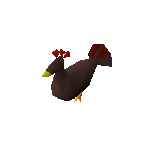
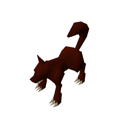
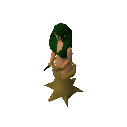
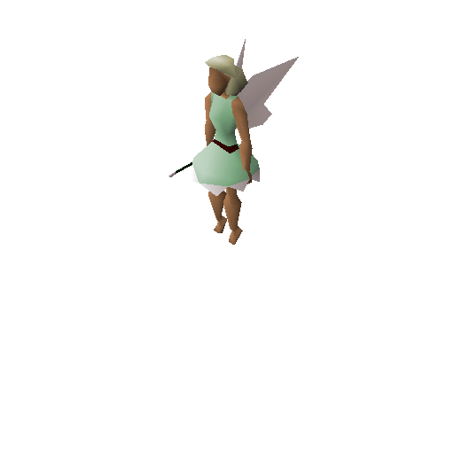

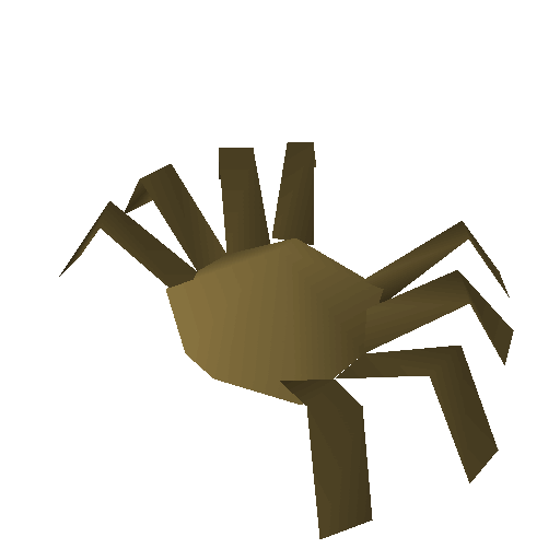
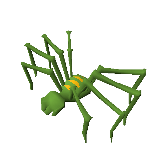
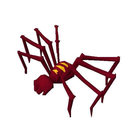
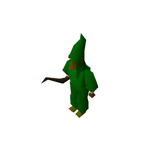
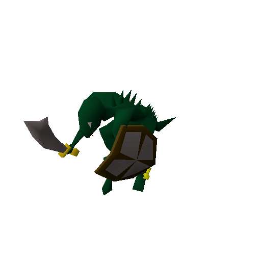
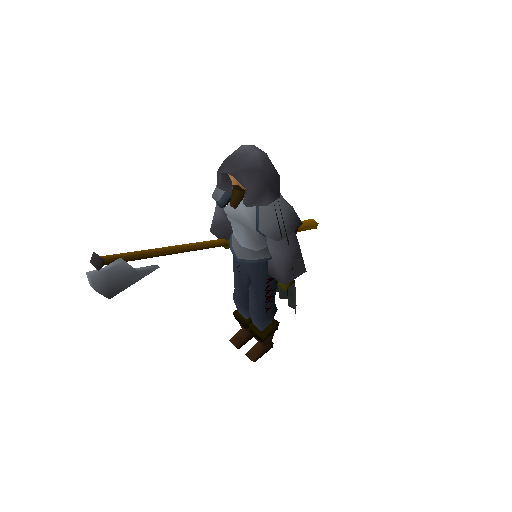
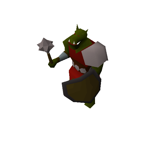

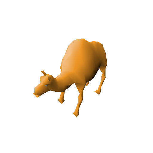
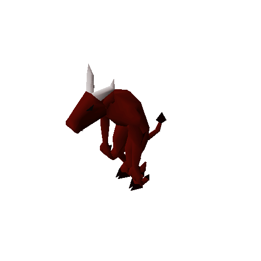

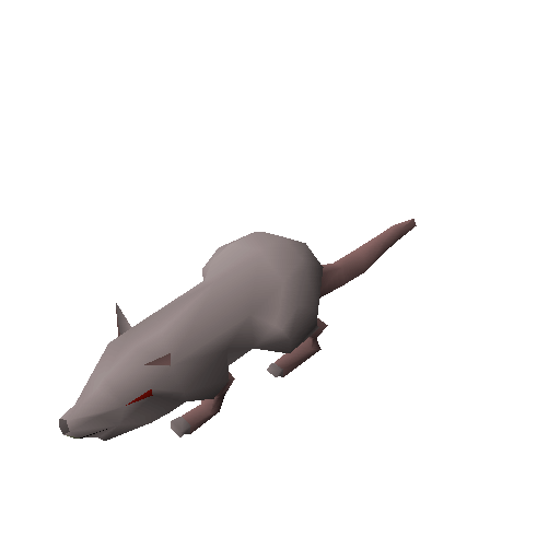
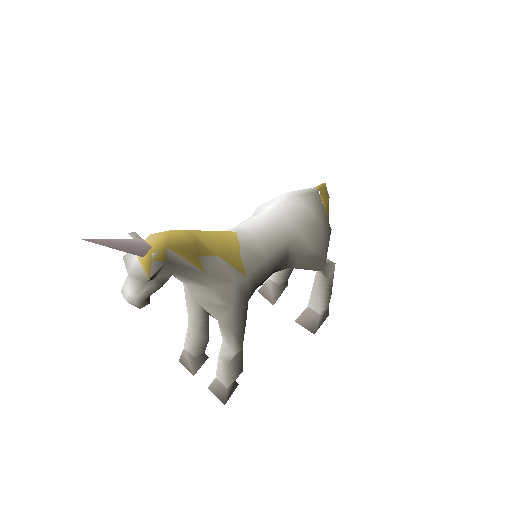
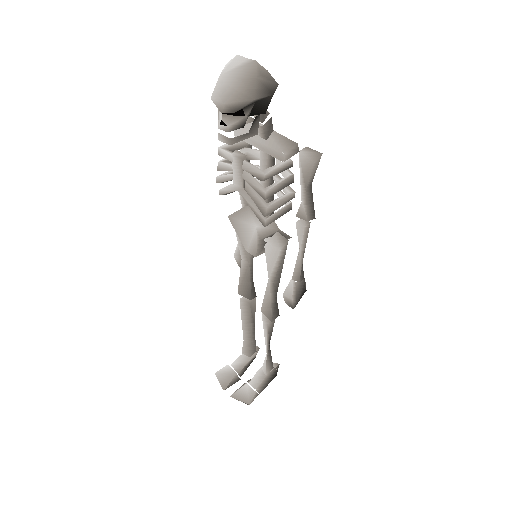
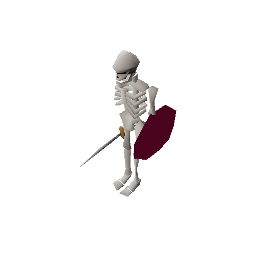
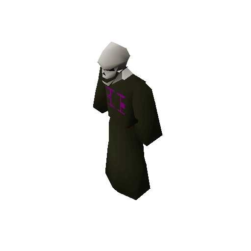
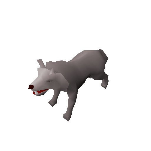

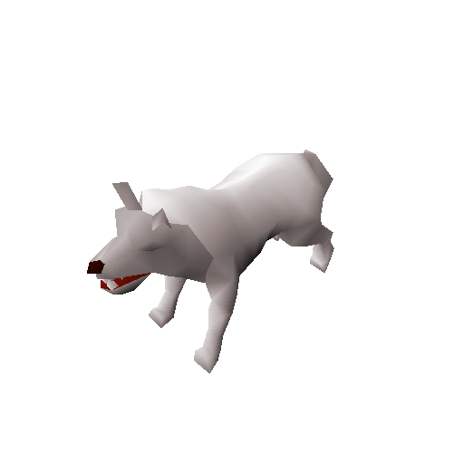
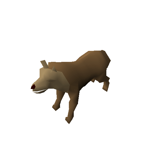
As of writing this post, I’m getting the tests set up for NPCs. So far so good.
Deadlines were missed
While I didn’t reach my self-imposed deadline I feel like I’ve made a ton of progress. I’m happy with how things are being laid out and still optimistic I’ll get this thing actually going. As for my milestones, I’ll have to push them out a couple of weeks until I get this client conversion completed since they are directly dependent on having you know, a client.
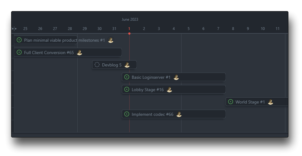
I’m excited to get some in-game screenshots going. I feel like I’m so close! Still, there are some pretty major portions of the client ahead of me, like pretty much everything scene related. Hopefully with all the models and rasterization looking the way it should, tying the scene together shouldn’t be such a big ordeal….right?
Here are the remaining tasks:
What do you think?
I’m interested to read your opinions on my posts. I’m always looking to improve my writing skills or readability! Any and all constructive feedback is appreciated, message me on Discord “medieval.software” or email me.
There are a few things I’m aware of that I’ve yet to find a solution for:
- Inconsistent graphs/diagrams
- My diagrams are all over the place.
- I’m thinking of using the same frontend that the Rune Synergy client will use to make interactive graphs and examples! It would be cool to let my readers in on some additional technicalities they can infer from just playing with these tools.
- A mixture of technical/non-technical information
- Every time I make a post, my goal is to take technical topics and break them down. Sometimes I feel like I’ve only further mystified the explanations though!
- If my explanations haven’t been clear enough, please reach out and leave a comment! I will definitely write a follow-up post to clarify.
As always, thanks for reading. I hope you’re as excited to see Rune Synergy as I am! Join the discord to follow along!